Assembly #
Once you have all the mechanic components printed and all the electronics soldered together, it’s time to assemble the scanner.
Power plug into chassis #
This step isn’t absolutely necessary but I highly recommend gluing the
scanner-power-supply PCB into its place inside the purple piece of the
chassis. Make sure the power plug is facing outwards.
Chassis assembly #
The following video walks you through the entire process of assembling the chassis.
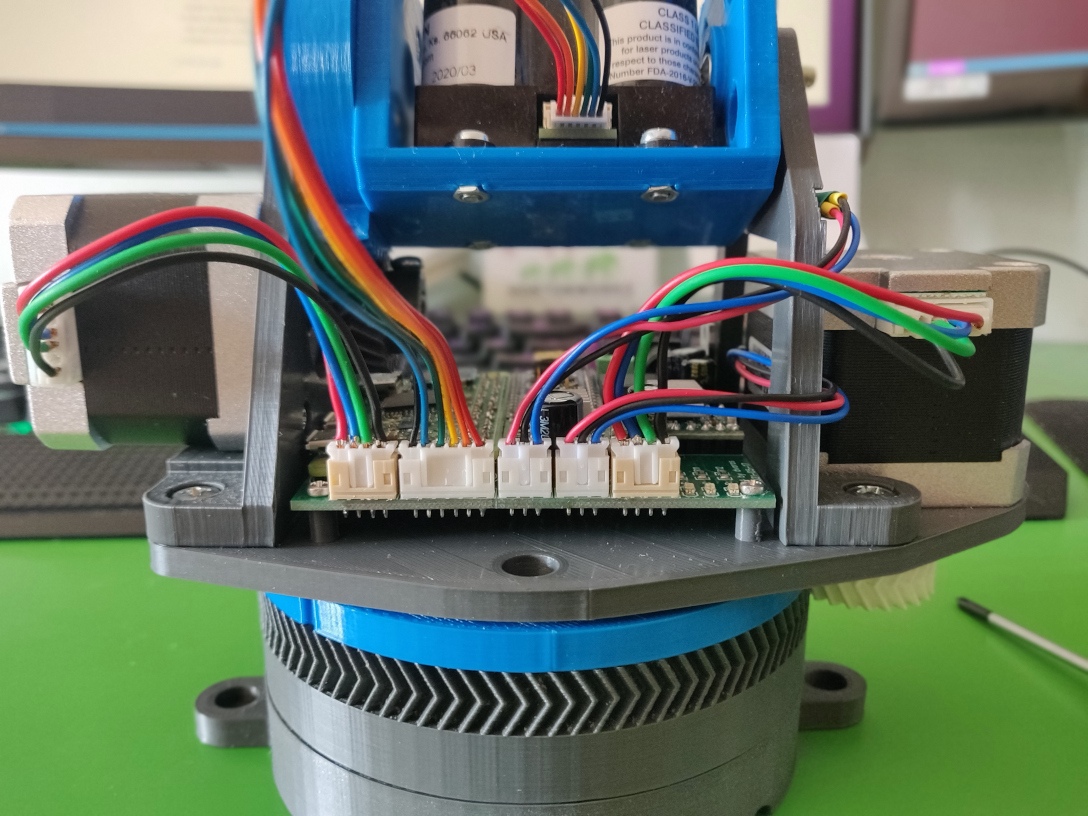
Cables #
Hook up everything using the cables that you’ve made.
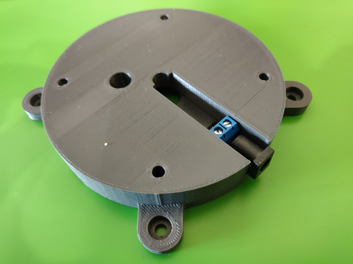
- Push the Hall sensor with the longer cable into its hole on the plate
(
greenpiece). Pay attention to the correct orientation, the flat side should be facing downwards. Lead the cable back to the its connector (labeledHALLX) tucking it in between the motor on the plate and the idle leg. - Push the Hall sensor with the shorter cable into its hole on the idle leg.
Pay attention to the correct orientation, the flat side should be facing
inwards. Connect to the
HALLYconnector. - Hook up both motors with their cables. The motor mounted on the plate (
greenpiece) should be connected toMOTXand the one on the driver leg toMOTY. - Connect the Lidar to the
LIDARconnector.
Conclusion #
Congratulations, you’re done with the assembly! At this point you can power up the scanner via the connector on the side of the chassis and continue with the software setup.