Electronics #
This page walks you through obtaining and putting together all the electronic components required for building a 3dasd scanner.
Ordering everything #
You need to get the following:
- two PCBs (main and power supply) with a bunch of electronic components
- two sets of NEMA 17 stepper motors and A4988 drivers
- a Garmin LIDAR-Lite v3
- a Raspberry Pi Zero W
- an Arduino Nano
- a slip-ring
- a 12V 2A power supply
- wires for making the cables
Getting the PCBs #
Check with me first!
Since you can only order 5+ PCBs from JLCPCB, I happen to have some extras! I’d be more than happy to send them your way so you don’t have to order more PCBs than you need. Get in touch!
You need to get two PCBs: the scanner and the scanner-power-supply. Both designs are available in the lidar-pcb Github repository. You could order PCBs with the Gerber files stored there from any manufacturer.
The following describes the process of ordering from JLCPCB. It’s probably the easiest option as the designs include parts that are availble in their inventory so you can order assembled PCBs.
Start at the JLCPCB order page. Click on
Add gerber file and upload the Gerber file you’ve downloaded from
here.
The default options should work, you can leave them as is:
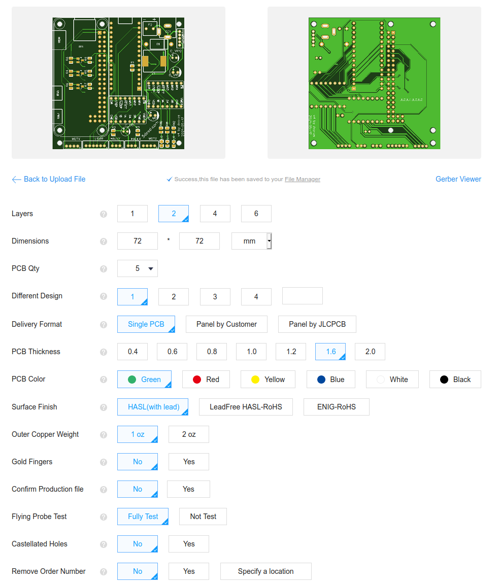
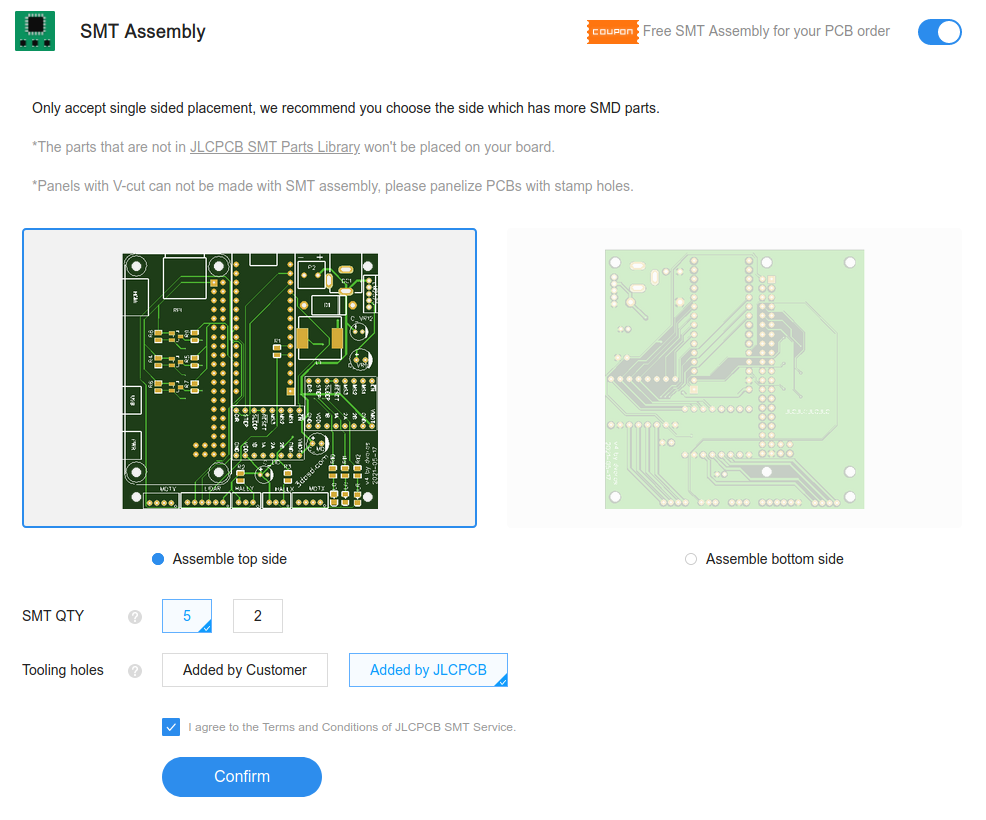
Enable the SMT assembly option and select how many of the PCBs you want
assembled:
Click Confirm to proceed to the next page where you need to upload the BOM
and CPL files downloaded from
here (BOM)
and
here (CPL).
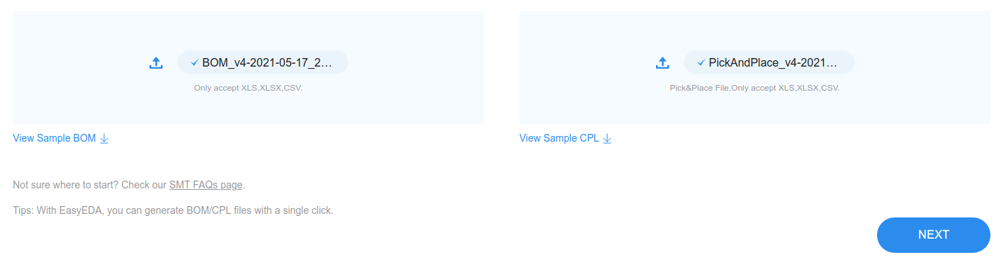
Hit NEXT to continue. You will be presented with a list of parts that JLCPCB
will solder onto the board.
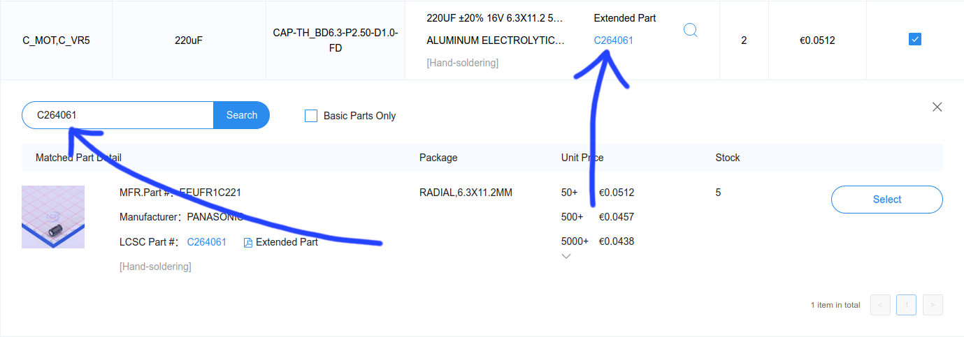
Inventory shortage for some parts?
Depending on their inventory you may find that some parts are not available (“Inventory shortage”). You can try replacing these with equivalent parts (connectors with different color, other brand) using the magnifying glass icon in that row.
I’ve found that some items are avaible even if they’re displayed as “Inventory
shortage”. Try to search for the same part using it’s part ID first (the
CXXXXXX number).
JLCPCB isn’t selling the following components, it’s okay that you see “No part selected” for A4988, Raspberry Pi Zero, arduino_nano:

If you’re happy with the parts list, hit NEXT to continue. Then review the
placement, it should look something like this:
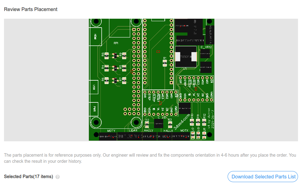
If you’re satisfied with the list of parts, continue with SAVE TO CART. Now
you have the “main PCB” (scanner) in your cart. It’s time to repeat the same
process with the “power plug PCB” (scanner-power-supply). Go to the
order page and do the same thing but this
time you should upload
this Gerber file.
The power plug PCB is too small for automated assembly. You won’t be able to
enable SMT assembly and will need to separately order parts for this PCB (see
below).
Once you’re done with the second PCB, finish your order with Secure Checkout.
Connectors and Hall sensor #
You need to order the following from LCSC (or your local store):
3x JST PH-6 male: one for the LIDAR connector and two for the motors2x JST PH-4 male: for the motors2x JST PH-3 male: for the Hall sensors28x JST PH crimping terminals: for the connectors above (get more, they’re easy to screw up!)1x screw terminal: for thescanner-power-supplyPCB1x 5.5-2.0MM DC plug: for thescanner-power-supplyPCB2x TLE4905 unipolar Hall sensor
Download the parts list from here and upload with the LCSC BOM tool
Select “LCSC Part number” above the first column and “Quantity” above
“Order Qty.” then click Next:
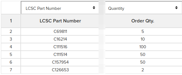
Review the list of components. The quantities in the BOM should be enough to
complete the minimum of 5 scanner-power-supply PCBs you’ve ordered in the
previous step and to assemble a single scanner. Adjust the quantities if
you need more (or less)!
If you’re happy with the list, hit Add to Cart, then go to your cart and
finish your order.
Rest of the modules #
Unfortunately the rest of the electronics are not available from a single online store, so you’ll need to find the best place you can get them. Depending on your location you can try ordering from Amazon, AliExpress or even better, your favorite local electronics shop.
Here’s what you need:
| Item | Notes |
|---|---|
| Garmin LIDAR-Lite v3 | v3 HP might also work but I haven’t tested that. |
| 2x 1.8deg NEMA 17 stepper motors | Get two! Make sure you get ones with 1.8deg step angle. I’ve tested with 0.4Nm torque motors, but that’s probably overkill, especially for the Y axis. |
| 2x A4988 stepper drivers | Get two! Also available from other manufacturers. |
| Raspberry Pi Zero W | Make sure you get the W kind for WiFi access. Try to get one without the header pins, because you’ll need those to be on the bottom. |
| Arduino Nano | Or anything compatible. |
| Slip-ring | The chassis is designed to fit SRC022A-6 or SRC022A-12 but can be modified relatively easily to fit something similar. If you can’t get these, make sure yours have at least 2 wires and is rated for at least 2 amps and 12 volts. |
| 12V 2A DC power supply | With 5.5*2.5mm barrel DC plug. |
| ~2 meters of AWG 24 wire | Should fit into the JST PH connector’s crimping terminal. Preferably in four colors (red, black, blue, green). |
| Crimping tool for JST PH connectors | You might be able to assemble the cables without this (video) but it makes your life a lot easier if you can borrow one. |
| 40 pin male 2-row header pin for the Raspberry | If you were able to get a Raspberry without the pins. (solderless connectors maybe?) |
Soldering #
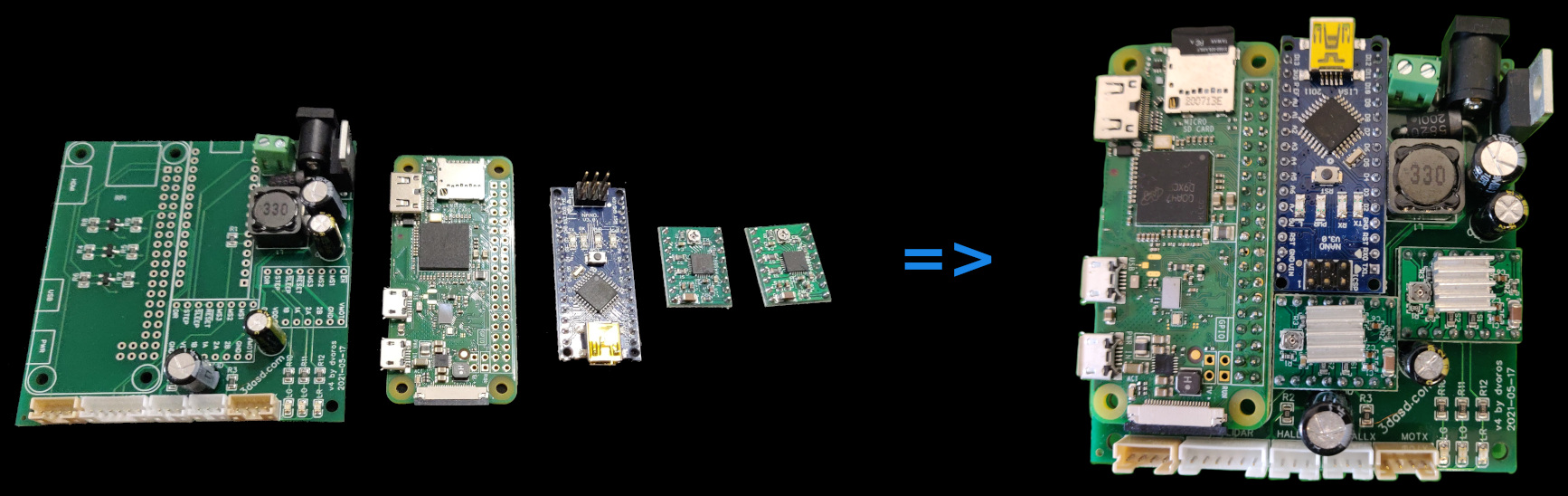
scanner PCB #
You need to solder the pin header on the Raspberry Pi and solder it onto the main PCB along with the Arduino Nano and the two A4988 boards. Pay attention to the correct orientation, refer to the image below.
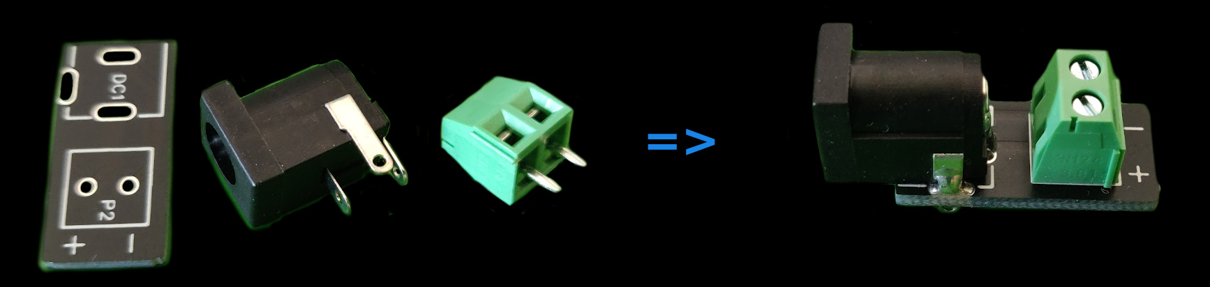
scanner-power-supply PCB #
Solder the DC plug and the screw terminal on the PCB. Screw terminal’s input should be facing away from the plug to be accessible.
Calibrating #
A4988 motor current tuning #
WARNING! Don’t hook up your motors to the board until you’ve completed this step!
You need to tune the A4988 drivers to match your stepper motors' current ratings. There’s a pot on the A4988 driver board that lets you adjust the maximum current delivered to the motor. Power up the PCB plugging the 12V power supply into the on-board plug, then follow this guide.
Cables #
JST connectors #
You need to craft five cables using the JST PH connectors. The LIDAR cable comes with the LIDAR, you only need to replace the original connector on the non-LIDAR side with a 6-pin JST PH connector.
Here’s a video tutorial for crimping the terminals with and without a crimping tool.
Refer to the image below for the connections:
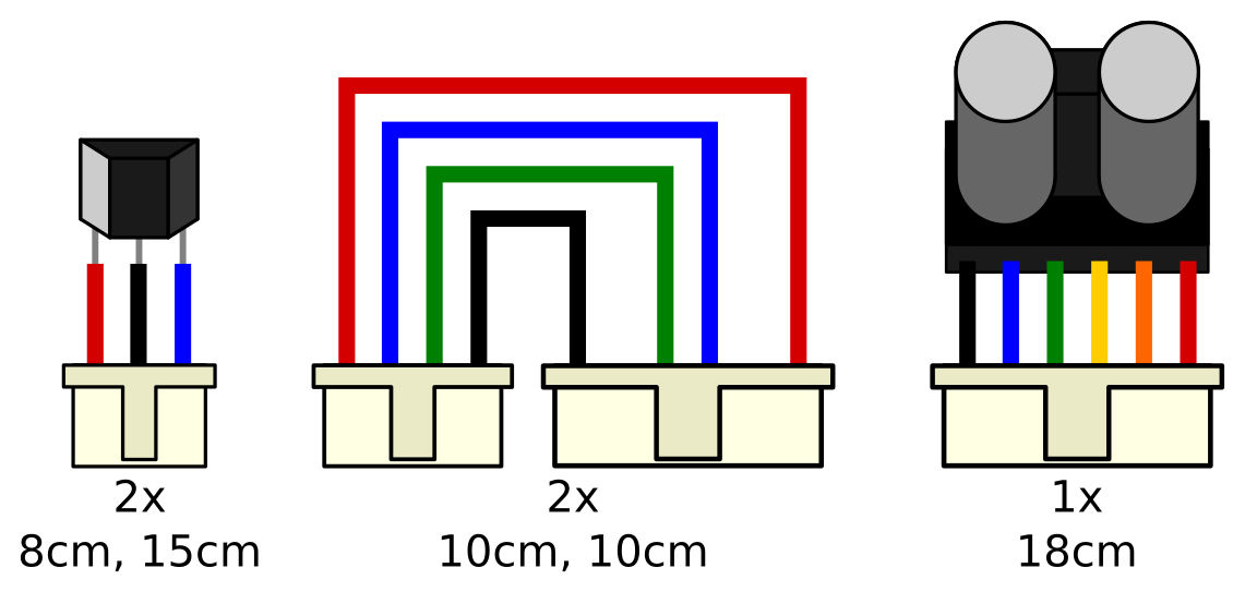
Hall sensors
Solder three cables to the three legs of the sensor. Use insulation sleeves or tape to make sure the three legs won’t touch.
Motors
Make sure you connect to the right places on the 6-pin side. 2nd and 5th places are supposed to be empty.
LIDAR
Cut the original connector from the LIDAR cable leaving around 18cm of the wires. Don’t remove the connector that goes into the LIDAR!
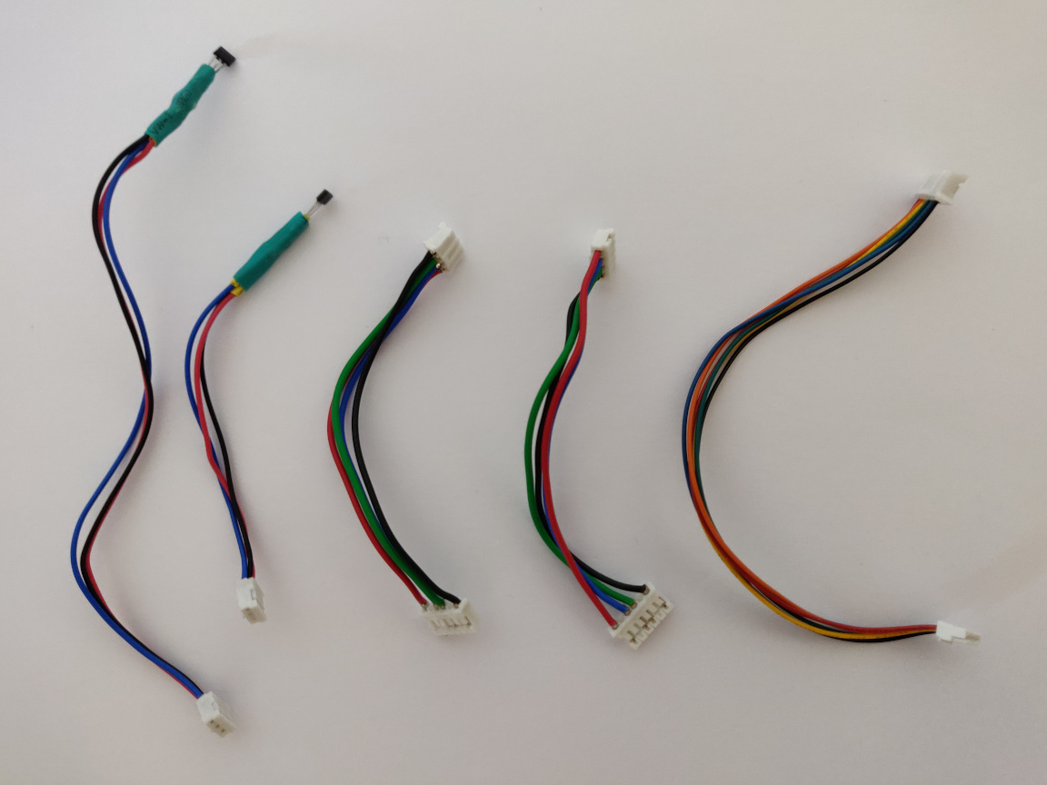
Here’s how my cables turned out, but I’m sure you can do better! (;
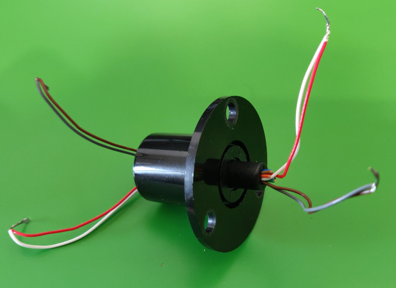
Slip-ring #
Only two cables are required, you can remove the rest. Make sure you keep the same colors on both ends! You could also join two cables to make sure they can carry enough current (2A max). Cut the cables to around 8cm length. You can also cut them once they’re in place during the assembly.
Conclusion #
Congratulations, you’re done with the electronics! You’re past the worst part, the cables assembly. (: Get your 3D printer ready and continue with the mechanics.