Mechanics #
This page walks you through obtaining all the mechanical parts required for building a 3dasd scanner. Most of the chassis can be 3D-printed, but there are a few metal pieces that hold everything together.
The metal parts #
You need a couple nuts and bolts and also some ball bearings and magnets. Here’s the shopping list:
| Item | Quantity |
|---|---|
| M2 nut | 3 |
| M3 nut | 10 |
| M4 nut | 13 |
| M2 10 bolt | 3 |
| M3 6 bolt | 2 |
| M3 8 bolt | 4 |
| M3 12 bolt | 4 |
| M4 10 bolt | 4 |
| M4 16 bolt | 1 |
| M4 20 bolt | 1 |
| M4 25 bolt | 3 |
| M4 40 bolt | 4 |
| 50x72x12 bearing | 1 |
| 6x13x5 bearing | 3 |
| 3x2 disk magnet | 2 |
Understanding the dimensions
50x72x12bearing means:
- 50mm inner diameter (“bore diameter”)
- 72mm outer diameter
- 12mm width (“raceway width”).
M4 25bolt means:
- M4 metric bolt (4mm outer diameter)
- 25mm long (nominal length, without the head)
3x2disk magnet means:
- 3mm diameter
- 2mm height
Bolt heads
I’m using
DIN7985bolts but anything similar should work fine.
Magnets
3x2and3x1.5should also work. Pay attention to the correct (axial) magnetization!
Can't get these exact sizes?
Having bolts a few millimeters shorter/longer should work okay in most places. Different bolt head and nut types should also work if they fit well into the slots designed for them. The next section describes 3D-printing a test-fit model where you can test your nuts+bolts+magnets.
The bearing dimensions are less forgiving, but you can customize the chassis to work with your bearings if necessary. Keep on reading for details!
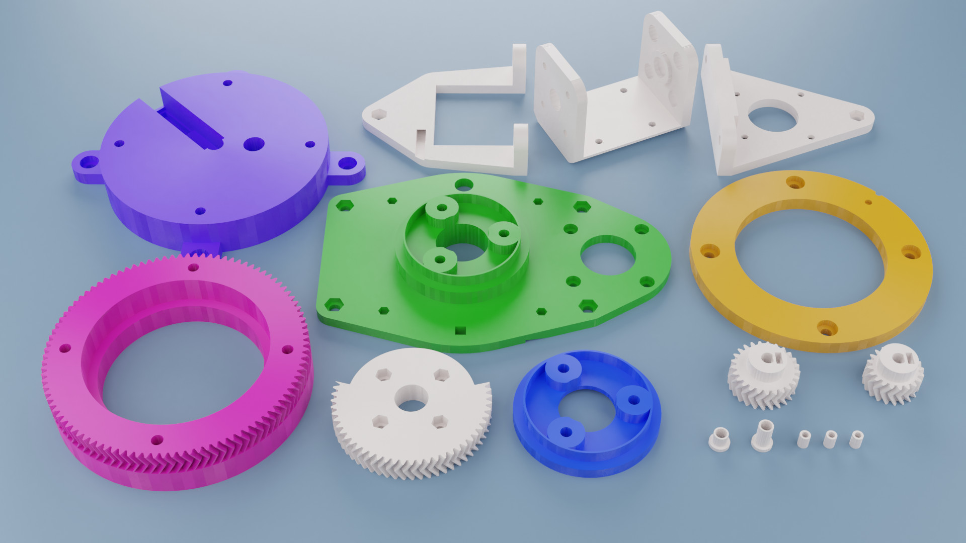
3D-printing the chassis #
Most of the scanner’s chassis is 3D-printed. You can print the following 16 pieces yourself or find a local shop where you can get them printed:
Getting the models #
You can download all the STL files from
here.
all-stl.zip has everything packed up.
The test-fit piece #
Start by printing the test_nuts_and_bolts piece. It’s a small piece
with all the slots for your nuts and bolts and also for a magnet. Use this to
validate if your parts will fit into the holes designed for them.
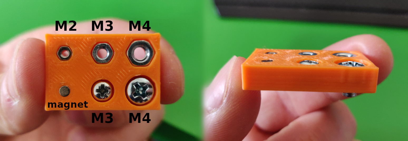
What to look out for:
- every piece should rest below the surface
- M2 nut should be a tight fit that won’t fall out even if it’s upside down and moved around
- all the other nuts and heads can be a little more loose
- the magnet should be a tight fit, but it’s also okay if you glue it into place
Customization #
If you can’t get the right nuts/bolts, you can try customizing the 3D models for the chassis pieces to work with your hardware. You can download the OpenSCAD source for the models from here or view it on Thingiverse here. Hit the “Open in Customizer” button to set your sizes.
Printing the pieces #
If you’re satisfied with the test-fit results, you can start printing the pieces. Here are some general recommendations for the slicer settings:
.2mmlayer height should be small enough to get accurate pieces- Parts shouldn’t bend! Use at least
20%infill and.8mmwall/top/bottom thickness. - The image above shows every piece in the orientation that they’re supposed to be printed, refer to that!
- Use support for the embedded nut/bolt sockets! You should be able to push them out from the other side.
The table below has some recommendations on the print settings for the individual pieces:
| Piece | Quantity | Notes |
|---|---|---|
pink | 1 | No supports. Print slower to get accurate gears. |
purple | 1 | Needs support for the nut sockets. |
orange | 1 | No supports. |
green | 1 | Needs support for multiple sockets. |
blue | 1 | Needs support for the entire inner circle. Consider printing on a raft. Won’t be visible from the outside, don’t worry if it’s ugly! |
x_driver_gear | 1 | No supports. Print slower to get accurate gears. |
y_driver_gear | 1 | No supports. Print slower to get accurate gears. |
y_gear | 1 | No supports. Print slower to get accurate gears. |
mount | 1 | Needs support for the sockets. |
idle_leg | 1 | Maybe you can get away without support. |
driver_leg | 1 | Needs support for the sockets. |
y_gear_plug | 1 | Might require some extra build plate adhesion (raft or brim). |
y_bearing_plug | 1 | Might require some extra build plate adhesion (raft or brim). |
pcb_bottom_spacer | 3 | Print three! Might require some extra build plate adhesion (raft or brim). |
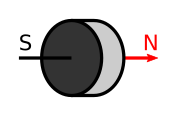
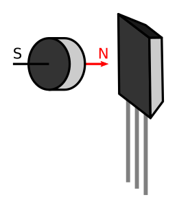
Adding the magnets #
The mount and orange pieces have tiny sockets for the magnets. Push the
magnets into those holes and glue them into place if necessary. Make sure that
the north pole of the magnet is facing outwards (towards the future Hall
sensor)!
Here’s an article
that helps you determine the polarization of your magnets.
Conclusion #
Congratulations, you’re done with the mechanical parts! You have everything to assemble the scanner! Head over to the assembly page.